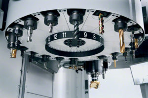
Looking something like a drill press, a milling machine uses a cutting tool that moves in all three dimensions, removing material to achieve the desired part shape. The cutting tool usually rotates about an axis that is perpendicular to the table that holds the material to be cut. A cutting tool protrudes down from a rotating spindle. A block of material is placed on a moving table below the cutter. While the cutting tool turns, a computer controls the vertical (Z axis) motion of the cutter and the horizontal (X and Y axis) motion of the block of material. The cutter is guided to move through the material, removing portions to create shapes. Additionally, the material can be turned to various orientations in the middle of the process and cutting tools of various shapes can be used.
Cutting tools
Some common cutter shapes include:

Referring to the above images :
Chamfer end mill – creates 45 deg bevels on the top edge of a wall or recess
Plain endmill – used for most milling – creates walls with straight 90 deg edges and sharp corners at the bottom of recesses.
Ball mill – creates rounded edges at the bottom edge of a recess
Grooving end mill – creates rectangular grooves in side walls
Rounding end mill – creates rounded edges at the top edge
Angle end mill – creates walls at angles other than 90 deg
and, not shown, a conventional drill
The material is usually removed by both the end and the side of the cutting tool.
Setup tooling
Although setup tooling is mainly software, custom jig tooling is often required for work holding.
Materials
This machining process can handle most rigid materials including most metals: Aluminum, Stainless Steel, Copper, Steel, Brass, Titanium, Sterling Silver, Bronze, etc.; hard plastics and other materials: Nylon, Acetal, Polycarbonate, Polystyrene, Acrylic, Fiberglass, Carbon fiber, PTFE, ABS, PVC, etc.
Advantages
Milling has several advantages over other manufacturing processes. It is cost effective for short runs. Complex shapes and high dimensional tolerances are possible. Smooth finishes can be achieved. CNC milling can produce almost any 2D or 3D shape provided that the rotating cutting tools can reach the material to be removed. Examples of parts include engine components, mold tooling, complex mechanisms, enclosures, etc.
Design Considerations for CNC Milling
Avoid flimsy shapes.
Providing corner radius of 10% or more of wall height is ideal.
Provide shapes that are practical to hold during machining, such as straight edges.
Generates a cut surface with a visible pattern resulting from the rotation and movement of the cutter.
As the milling process applies pressure to the material, weak shapes are difficult to machines, such as long thin shapes and thin walls.
Cost Reduction
Cost reduction options include reducing the amount of material removed, limiting complexity, avoiding intricate features and making shapes that are easy to hold.
We stock a wide variety of materials, use state-of-the-art machines and diligently follow all design specifications. We continually strive to improve and optimize our processes and maximize customer convenience. Our customers range from investors to businesses to government agencies. We are focused on quality and customer service.
